Table of Contents >> Show >> Hide
- Why Fiber Optic Cable Testing Matters
- Tools You Need to Test Fiber Optic Cables
- How to Test Fiber Optic Cables: 9 Steps
- Step 1: Identify the Cable Type and Test Requirements
- Step 2: Inspect the Fiber Connectors Before Connecting Anything
- Step 3: Clean Adapters, Test Cords, and Reference Cables
- Step 4: Perform a Visual Continuity Test
- Step 5: Verify Polarity
- Step 6: Set a Reference for Loss Testing
- Step 7: Measure Insertion Loss with an Optical Power Meter and Light Source
- Step 8: Use an OTDR to Locate Faults and Characterize the Link
- Step 9: Record Results and Create a Test Report
- Common Fiber Optic Cable Testing Mistakes
- Example: Testing a Simple Duplex Fiber Link
- Field Experience: Practical Lessons from Testing Fiber Optic Cables
- Conclusion
Fiber optic cables are the quiet overachievers of modern networking. They do not buzz, hum, or dramatically announce themselves. They simply carry huge amounts of data as light, then get blamed the moment a connection slows down. Testing fiber optic cables is how you find out whether the cable is innocent, guilty, or merely suffering from a dusty connector that has been treated like a garage floor.
Whether you are working in a data center, office building, campus network, telecom room, or home lab that somehow became “enterprise-grade” over the weekend, proper fiber optic cable testing helps confirm continuity, polarity, insertion loss, optical power, link length, and fault location. In plain English: it tells you whether light can travel through the cable cleanly enough for the network to work.
This guide explains how to test fiber optic cables in 9 practical steps, using common tools such as a visual fault locator, fiber inspection scope, optical power meter, light source, optical loss test set, and OTDR. The goal is not to turn you into a walking standards manual. The goal is to help you test smarter, avoid rookie mistakes, and keep your network from behaving like it had three espressos and a panic attack.
Why Fiber Optic Cable Testing Matters
Fiber optic cable testing is not just a “nice-to-have” task after installation. It is the difference between a link that works today and a link that can be trusted tomorrow. Fiber links can fail because of dirty end faces, tight bends, cracked fibers, bad splices, mismatched connectors, poor polarity, damaged patch cords, or incorrect equipment settings. Some problems are obvious. Others hide quietly until a high-speed application exposes them with the subtlety of a fire alarm.
Good testing creates a baseline. When the link is new, you record optical loss, length, polarity, connector condition, and OTDR traces if needed. Later, when someone says, “The network feels slow,” you can compare current readings with the original results instead of guessing, blaming the switch, blaming the cable, blaming the intern, and then eventually discovering dust.
Tools You Need to Test Fiber Optic Cables
Before starting, gather the right tools. At minimum, you may need a fiber inspection microscope or digital inspection probe, approved fiber cleaning supplies, a visual fault locator, a light source, an optical power meter, reference-grade test cords, mating adapters, and documentation software or a test report template. For certification and troubleshooting, an optical loss test set and an optical time domain reflectometer are often used.
Think of the tools like a medical kit. The inspection scope checks whether the connector face is healthy. The cleaner removes contamination. The visual fault locator finds obvious breaks or routing problems. The power meter and light source measure how much light gets through. The OTDR acts like a detective, showing where loss, reflection, splices, bends, or breaks may exist along the fiber.
How to Test Fiber Optic Cables: 9 Steps
Step 1: Identify the Cable Type and Test Requirements
Start by identifying what kind of fiber you are testing. Is it single-mode or multimode? Is the connector LC, SC, ST, FC, or MPO? What wavelength should be used? Common multimode testing wavelengths include 850 nm and 1300 nm, while single-mode links are commonly tested at 1310 nm and 1550 nm. The test wavelength should match the system or standard being verified.
Next, define the purpose of the test. Are you verifying a new installation, troubleshooting a failed link, checking a patch cord, certifying a structured cabling system, or locating a break? The answer determines which tools you need. A quick continuity check may only require a visual fault locator. Certification usually requires Tier 1 testing with an optical loss test set or light source and power meter. Deeper troubleshooting may require OTDR testing.
Do not skip this planning step. Testing without knowing the cable type is like measuring a doorway without knowing whether you are moving a chair, a refrigerator, or a grand piano. The numbers only matter if they are measured against the right expectations.
Step 2: Inspect the Fiber Connectors Before Connecting Anything
Dirty fiber connectors are one of the most common causes of optical network problems. Dust, oil, lint, and tiny particles can block light, increase loss, scratch the end face, or create reflectance problems. The annoying part is that contamination may be too small to see with the naked eye. The even more annoying part is that mating a dirty connector with a clean one can make both dirty. Congratulations, now the problem has socialized.
Use a fiber inspection probe or microscope to examine the connector end face. Look for dust, scratches, chips, cracks, residue, or oil. Many modern inspection tools can provide pass/fail results based on recognized end-face inspection criteria. If contamination is found, clean the connector with approved dry cleaning tools or wet-to-dry methods recommended for fiber optics.
After cleaning, inspect again. The best rule is simple: inspect, clean if needed, and inspect again. Never assume a connector is clean because it has a dust cap. Dust caps are helpful, but they are not magical force fields. Some of them are dusty enough to need their own dust cap.
Step 3: Clean Adapters, Test Cords, and Reference Cables
Testing accuracy depends heavily on the condition of your test setup. A perfect installed cable can fail if your launch cord is dirty, damaged, or mismatched. Clean all test cords, adapters, and connector interfaces before use. Use reference-grade test cords when measuring insertion loss, especially when results will be used for certification or acceptance testing.
Match the fiber type of your test cords to the link under test. Do not test a multimode cable with single-mode launch cords or mix connector grades without understanding the impact. Also check that connectors are fully seated. A slightly loose connector can create a misleading loss reading and send you on a troubleshooting adventure you did not sign up for.
Good technicians treat test cords like precision instruments, not spare shoelaces. Keep them capped, clean, labeled, and replaced when worn. A bad reference cord can make every cable look bad, which is a very efficient way to waste an afternoon.
Step 4: Perform a Visual Continuity Test
A visual continuity test confirms that light can travel from one end of the fiber to the other. Connect a visual fault locator or visual fiber tracer to one end of the cable and check the far end for visible red light. This test is useful for identifying fiber routing, confirming that the cable is not completely broken, and checking basic polarity in duplex links.
If no light appears at the far end, check intermediate patch panels, splice trays, couplers, and connection points. The problem may be a disconnected patch cord, wrong port, bad adapter, broken fiber, or incorrect labeling. In many buildings, wrong labeling is not a defect; it is practically a local tradition.
A visual fault locator can also reveal tight bends, cracked fibers, or high-loss points in short cable runs. If red light leaks through the jacket or appears at a connector, bend, or splice area, you have likely found a fault. However, remember that a visual test does not measure performance. It only proves that visible light can pass or escape. A cable can pass a continuity test and still fail insertion loss requirements.
Step 5: Verify Polarity
Fiber polarity ensures that the transmitter on one end connects to the receiver on the other. In duplex fiber links, transmit and receive paths must be crossed correctly. In MPO systems, polarity can become more complex because multiple fibers are arranged in a single connector. If polarity is wrong, the link may look physically connected but still refuse to communicate, like two people talking into microphones connected to no speakers.
Use a visual tracer, optical loss test set, or polarity-capable fiber tester to confirm that each fiber lands where it should. Compare the results with the network drawings, patch panel labels, and cabling method. For MPO cabling, confirm whether the system uses Method A, Method B, Method C, or another documented design.
Polarity testing is especially important after moves, adds, changes, cassette swaps, and emergency “quick fixes.” Quick fixes are often where polarity goes to retire.
Step 6: Set a Reference for Loss Testing
Before measuring insertion loss, set a reference using your light source and optical power meter or optical loss test set. The reference establishes the baseline power level so the tester can calculate how much signal is lost through the cable under test. Follow the manufacturer’s procedure carefully, because reference setup is one of the biggest sources of bad test data.
Common reference methods include one-cord, two-cord, and three-cord references, depending on the connectors, standards, and test configuration. For many certification workflows, the one-cord reference is preferred because it can provide lower measurement uncertainty when properly performed. Whatever method is used, document it clearly.
Do not disconnect the reference connection after setting it unless the procedure tells you to. If you disturb the reference cord, clean again and reset the reference. Fiber testing can be unforgiving, and the meter does not care that you were “pretty sure” nothing changed.
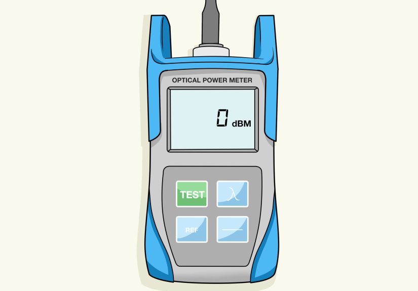
Step 7: Measure Insertion Loss with an Optical Power Meter and Light Source
Insertion loss testing measures how much optical power is lost as light travels through the fiber link. Connect the light source at one end and the optical power meter at the other. Choose the proper wavelength and test direction. For some projects, bidirectional testing is required, meaning the link is tested from both ends and the results are recorded.
The measured loss is shown in decibels. Lower loss is generally better, but the real question is whether the result fits within the link loss budget or application requirement. A short multimode link in a data center may have a very tight allowable loss, while a longer single-mode outside plant link may have different expectations based on length, splices, connectors, and equipment power budget.
Compare the measured value with the expected loss. The expected loss usually includes fiber attenuation, connector loss, splice loss, and any passive components. For example, a link with several connectors, a few fusion splices, and a long cable run should naturally have more loss than a short patch panel connection. If the measured loss is much higher than expected, inspect and clean again, check bends, verify connections, and then investigate with an OTDR if needed.
Step 8: Use an OTDR to Locate Faults and Characterize the Link
An optical time domain reflectometer sends pulses of light into the fiber and analyzes the light that returns. The result is a trace showing distance, loss events, reflective events, splices, connectors, bends, breaks, and the end of the fiber. OTDR testing is especially useful for long links, outside plant cabling, splice verification, fault location, and documentation.
Use a launch cable so the OTDR can properly see the first connector. A receive cable may also be used to evaluate the far-end connector. Without proper launch and receive cables, the OTDR may hide or misrepresent events near the beginning or end of the link. That is like asking a security camera to identify someone standing directly behind it.
Set the OTDR for the correct fiber type, wavelength, pulse width, range, index of refraction, and averaging time. Poor settings can create confusing traces or inaccurate event readings. When precision matters, test from both directions and average event loss values. OTDR results are excellent for troubleshooting and link characterization, but they do not replace proper insertion loss testing when certification requires Tier 1 results.
Step 9: Record Results and Create a Test Report
Documentation is the final step, and it matters more than many people want to admit. Record cable ID, fiber number, location, connector type, fiber type, wavelength, reference method, test direction, measured loss, length, polarity, inspection results, equipment model, calibration status, technician name, and test date. If OTDR testing was performed, save the trace files.
A good report proves that the cable met requirements at the time of testing. It also gives future technicians a baseline for troubleshooting. Without documentation, every later problem starts from zero. With documentation, you can compare today’s readings with the original readings and quickly identify whether the cable changed, the equipment changed, or someone “temporarily” rearranged patch cords six months ago and forgot to mention it.
Keep reports organized by project, building, floor, room, rack, panel, and port. Clear naming conventions are not glamorous, but neither is crawling behind a rack at 11:40 p.m. because “Fiber 12 maybe means the blue one.”
Common Fiber Optic Cable Testing Mistakes
The first major mistake is testing dirty connectors. Always inspect before connecting. The second mistake is using damaged or low-quality test cords. The third is choosing the wrong wavelength or fiber type setting. The fourth is relying only on a visual fault locator and assuming the link is good. The fifth is using an OTDR trace as a replacement for insertion loss certification when standards or project requirements call for OLTS testing.
Another common mistake is ignoring the loss budget. A number on a meter means very little without a pass/fail target. Always compare measured loss with the design requirement, application limit, or calculated budget. Finally, do not forget safety. Never look directly into a fiber end face, active connector, transmitter port, or visual fault locator output. Optical signals may be invisible, but your eyes are not interested in becoming test equipment.
Example: Testing a Simple Duplex Fiber Link
Imagine you are testing a duplex multimode fiber link between two network closets. First, you identify the fiber as OM4 multimode with LC connectors. The network uses 850 nm optics, so you plan to test at 850 nm and possibly 1300 nm if required by the project. You inspect both ends, find dust on one connector, clean it, and inspect again.
Next, you use a visual fault locator to confirm that Fiber A at Closet 1 appears at the expected port in Closet 2. Then you verify that transmit and receive are crossed correctly. After that, you set a reference with your optical loss test set and measure insertion loss. The result is within the allowable budget, so the link passes. You save the report, label the ports, and move on with your day like a professional who enjoys not being called back.
If the loss had been too high, you would clean and retest first. If the problem remained, you would check patch cords, adapters, bend radius, and connector seating. If still unresolved, you would use an OTDR to locate a high-loss event, bad splice, bend, or break.
Field Experience: Practical Lessons from Testing Fiber Optic Cables
In real-world fiber testing, the cable is not always the villain. Many failed links are caused by small, ordinary issues that look boring until they bring down a connection. One of the most common experiences is finding that a link fails loss testing, only to pass after proper cleaning. That does not mean the first test was useless. It means the test did exactly what it was supposed to do: it caught a condition that could have caused unstable performance later.
A useful habit is to slow down before speeding up. New technicians often want to plug in the tester immediately and start collecting numbers. Experienced technicians usually inspect first, clean carefully, verify the setup, and then test. It feels slower for the first few minutes, but it saves time because you avoid chasing false failures. Fiber testing rewards patience. It punishes assumptions with confusing readings and mysterious callbacks.
Another practical lesson is to protect your reference cords like they are expensive, because they are. A launch cord that gets dragged across a floor, stuffed into a tool bag, or left uncapped can become the hidden cause of repeated failures. When every cable starts showing suspiciously high loss, check the test cords before declaring the building haunted. Keep a known-good reference cord available and replace worn cords before they become tiny chaos machines.
OTDR testing also teaches humility. A trace may look dramatic, but interpretation matters. A reflective event may be a connector, a mechanical splice, or the end of the fiber. A non-reflective event may be a fusion splice or bend. A “ghost” event may appear because of strong reflections. The OTDR is powerful, but it is not a crystal ball. Good results require correct settings, proper launch cables, and an understanding of what the trace is showing.
Labeling is another field lesson that deserves more respect. A beautifully tested fiber link can still create trouble if ports are mislabeled. During testing, always confirm that the label on the panel matches the actual route and fiber number. Do not assume documentation is correct just because it is printed neatly. Some of the most elegant spreadsheets in the world contain lies with borders and shading.
When testing in active environments, communication is just as important as equipment. Before disconnecting anything, confirm whether the fiber is live and whether services are running. Use appropriate live-fiber identification methods when needed. Coordinate with network teams, maintenance windows, and site contacts. The fastest way to become unpopular is to unplug the wrong fiber during business hours and then say, “I was just testing.”
Finally, good fiber testing is about building confidence. A clean connector, a passing insertion loss result, correct polarity, a saved report, and a clear OTDR trace all tell the same story: this link is ready. That confidence matters when the network supports security cameras, medical systems, cloud access, production lines, financial transactions, or a video meeting where the CEO is already asking, “Can everyone hear me?”
Conclusion
Testing fiber optic cables is a structured process, not a guessing game. Start by identifying the cable and test requirements. Inspect and clean every connector. Verify continuity and polarity. Set the reference correctly. Measure insertion loss with the proper tools. Use an OTDR when you need to locate faults or document the link in greater detail. Finally, save clear reports so future troubleshooting has a reliable baseline.
The best fiber technicians are not the ones who rush through testing. They are the ones who create repeatable, trustworthy results. Fiber may carry data at the speed of light, but testing it well still requires human discipline, clean connectors, good tools, and a healthy suspicion of anything labeled “temporary.”