Table of Contents >> Show >> Hide
- What Is a Coax Stub Filter?
- The One Big Idea: Transmission-Line Impedance “Inversion”
- Stub Filter Types You’ll Actually Use
- Open vs. Shorted Stubs: Which Should You Build?
- The Minimal Math That Makes You Dangerous (In a Good Way)
- Worked Example: A Coax Notch to Calm Down FM Broadcast Interference
- Harmonic Suppression: The “Free” Extra Notches You Shouldn’t Ignore
- Where Coax Stub Filters Shine (and Where They Don’t)
- Practical Build Tips (So Your Stub Doesn’t Become Accidental Modern Art)
- Coax Stubs vs. PCB Stubs: Same Physics, Different Headaches
- Quick FAQ
- Hands-On Experiences: Lessons From the Land of “Why Is This Not Working?” (≈)
- Conclusion
A coax stub filter is the only kind of “wire to nowhere” that engineers will defend with a straight face.
It looks like a mistake: a T-connector, a short piece of coax, and… nothing at the end. Yet that “nothing”
can quietly murder an unwanted frequency while letting your desired signal stroll through like it owns the place.
If you’ve ever stared at a stub and thought, “That can’t possibly work”congrats, you have the correct instincts.
Now let’s upgrade them.
In this guide, we’ll break down how coax stubs behave, why quarter-wave lengths feel like magic (but aren’t),
and how to design practical notch and harmonic-trap filters you can build with common coax and connectors.
Expect real equations, real-world gotchas, and at least one gentle roast of “close enough” measuring tape.
What Is a Coax Stub Filter?
A stub is a short section of transmission line (coaxial cable, microstrip trace, stripline, etc.)
that branches off a main line and ends in either an open circuit (unterminated) or a
short circuit (center conductor bonded to shield). Because transmission lines store energy
and have distributed inductance/capacitance, their impedance changes with frequency. That means a stub can look like:
- a near-open at one frequency,
- a near-short at another,
- and a reactive “meh” everywhere else.
When you attach that frequency-dependent impedance in shunt (to ground) or in series
with the signal path, you get a filter. The most common coax-stub filters are notch (band-stop) filters
and harmonic traps.
The One Big Idea: Transmission-Line Impedance “Inversion”
Quarter-wave stubs: the open-to-short party trick
The reason stubs are famous is the quarter-wave effect. A transmission line doesn’t just carry a signal; it also
“transforms” impedances along its length. At one quarter-wavelength (λ/4) from a termination:
- an open termination transforms into an apparent short,
- and a short termination transforms into an apparent open.
This is why stubs can do double duty in RF systems: you can make something that is a DC short but an RF open (or vice versa),
which is incredibly handy for biasing networks, grounding, and filtering.
Why a “wire to nowhere” can notch a frequency
Put a stub on a T-connector so it sits in shunt with your signal line. At the frequency where the stub looks
like a short to ground, energy at that frequency gets dumped (reflected/absorbed by losses) instead of passing through.
Result: a notch.
Stub Filter Types You’ll Actually Use
1) Shunt notch (band-stop) stub
This is the classic: a main coax line with a T, and a branch stub that is either open or shorted at the far end.
At its target frequency, the stub’s input impedance becomes very low (or very high, depending on how you configure it),
creating a sharp attenuation feature.
Common use cases: killing an interfering broadcast band near a receiver front end, suppressing a single spur,
or taming a narrowband offender that’s driving your LNA into a bad mood.
2) Harmonic trap with a shorted λ/4 stub
A shorted quarter-wave stub can be arranged so it is effectively “invisible” at your fundamental frequency but becomes a
short to ground at a harmonic (or set of harmonics). This is popular in HF stations for harmonic suppression when you know
exactly what you want to keepand what you want gone.
Open vs. Shorted Stubs: Which Should You Build?
Open-circuit stubs
- Pros: Simple to buildno solder short at the end.
- Cons: The open end has fringing capacitance and “end effect,” so the electrically-correct length is often
slightly shorter than your tape measure suggests. Also, the open end can have high RF voltage at resonancekeep fingers and
metal tools away. - Best for: quick experiments, light-duty notches, and situations where sealing a shorted end is annoying.
Short-circuit stubs
- Pros: Better shielded, often more repeatable, and the short can be physically robust if done well.
- Cons: You must create a good RF short (low inductance). A sloppy braid pigtail can turn your “short” into a
mystery inductor. - Best for: harmonic traps, outdoor installs (when sealed), and “set it and forget it” builds.
The Minimal Math That Makes You Dangerous (In a Good Way)
Step 1: Find guided wavelength in coax
In free space, wavelength is λ = c / f. In coax, signals travel slower by the velocity factor (VF), so:
λcoax = (c / f) × VF
Step 2: Quarter-wave physical length
A quarter-wave stub length is:
L ≈ (c × VF) / (4f)
Where c is the speed of light (~3×10⁸ m/s) and f is frequency in Hz.
VF depends on the dielectric and is listed in the coax datasheet (don’t guessmanufacturers already did the homework).
Reality check: connectors, end effects, and “why is it off by 4%?”
In real builds, your resonance can shift because:
- connectors add electrical length,
- open ends have fringing capacitance,
- bends and nearby metal change effective dielectric environment,
- and your coax isn’t a perfect lossless line (no matter how passionately the catalog promised “low loss”).
Practical rule: cut slightly long, then trim while measuring. Coax is easy to shorten and annoying to un-shorten.
(Unless you enjoy buying more coax. No judgment. Mild judgment.)
Worked Example: A Coax Notch to Calm Down FM Broadcast Interference
Scenario: you have a VHF receiver (say, 2-meter band) and nearby FM broadcast stations (88–108 MHz) are hammering your front end.
A notch filter aimed at the FM band can restore sanity.
Pick a target notch frequency
If you want a single-stub notch centered roughly in the FM band, choose something like 98 MHz.
(If you need deep rejection across the entire 88–108 MHz range, you may use multiple stubs or a different topology.)
Compute an initial stub length
Suppose you’re using a common RG-58-type coax with VF ≈ 0.66. Then:
- Free-space quarter-wave at 98 MHz: (3e8) / (4×98e6) ≈ 0.765 m
- In coax: 0.765 m × 0.66 ≈ 0.50 m (about 20 inches)
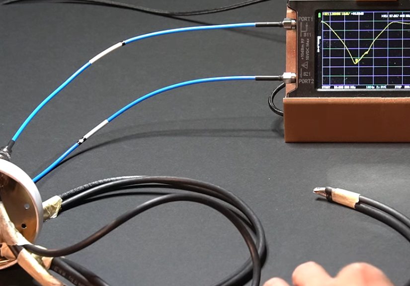
Build and measure
- Install a T-connector in your feedline.
- Attach the stub to the T. Start with a little extra length (say +2–3 cm).
- Measure S-parameters on a VNA if you have one; otherwise, use a spectrum analyzer + tracking generator, or even a decent antenna analyzer.
- Trim in small steps until the notch lands where you need it.
If you observe that the notch is too narrow or not deep enough, you have options:
add a second stub (carefully spaced), change stub impedance (different coax), or move to a purpose-built filter.
Multi-stub filters can reach impressive rejection but can also become sensitive to physical layout and spacingcoax is obedient,
but it has a personality.
Harmonic Suppression: The “Free” Extra Notches You Shouldn’t Ignore
Stubs are periodic. That’s not a flaw; it’s a warning label and a feature in the same sentence.
A shorted line’s input impedance repeats with frequency, meaning your stub may also affect harmonics.
Why a shorted λ/4 stub can be transparent at f0 but lethal at 2f0
For a shorted stub:
- At f0 where the stub is λ/4, the stub looks like an open at the feedpoint (minimal loading).
- At 2f0, the same physical length is λ/2, and a shorted half-wave looks like a short at the feedpointdumping that harmonic to ground.
That’s why shorted stubs show up in real HF station setups for harmonic suppression. The only catch: placement along the feedline
matters, because impedance varies along the line. Put the stub where it can actually “see” the harmonic energy you want to kill.
Where Coax Stub Filters Shine (and Where They Don’t)
They shine when…
- you need a narrow notch at a known frequency,
- you want a low-cost filter for an experiment,
- you’re dealing with a single bully signal (paging, broadcast, a specific spur),
- you’re building quick RF “plumbing” like traps, chokes, or bias structures.
They struggle when…
- you need wide stopbands with flat in-band performance,
- your system is multi-octave broadband,
- your environment changes (moving cables, temperature extremes) and you need tight repeatability,
- you need guaranteed specs for compliance (that’s when commercial filters earn their keep).
Practical Build Tips (So Your Stub Doesn’t Become Accidental Modern Art)
1) Use the datasheet velocity factor
VF is not universal. Different dielectrics (solid PE, foam PE, PTFE) yield different propagation speeds. Your coax manufacturer
already lists it. Use that number, not a forum post from 2009 that begins with “IIRC…”.
2) Keep the stub physically stable
If you tune a stub and then zip-tie it tightly to a metal rack, you just changed its environment.
Not always a disaster, but don’t be surprised if the notch wanders.
3) Treat the end termination like it matters (because it does)
For shorted stubs, make the short low-inductance: a clean bond of center to shield at the end connector or inside a metal cap.
For open stubs, consider sealing the end to keep moisture out (water changes dielectric properties and your notch will go sightseeing).
4) Measure like a grown-up (or at least like a curious goblin with tools)
A VNA is the gold standard, but you can still do meaningful work with simpler gear.
If you can sweep frequency and observe signal reduction at the output, you can tune stubs.
The key is consistency: same setup, same cable routing, small trims, repeat.
5) Watch power and voltage
Resonant structures can develop significant RF voltage/current at specific points. Open stubs can bite (electrically),
and high-power transmit chains can heat coax and shift behavior. If you’re filtering a transmitter output, use appropriate coax,
connector ratings, and common sense.
Coax Stubs vs. PCB Stubs: Same Physics, Different Headaches
On PCBs at microwave frequencies, “stubs” often appear as microstrip or stripline branches. Designers even use special shapes
like radial stubs to broaden bandwidth and manage fringing effects. The core idea is identical: you’re transforming impedance
with a known electrical length. The difference is that on a PCB, tiny geometry changes matter more, and you’ll often want EM
simulation rather than “trim and pray.”
Quick FAQ
Do coax stub filters work as band-pass filters?
They can, especially when you combine multiple stubs or use quarter-wave transformer sections, but the simplest and most common
coax-stub use is notch/band-stop or harmonic trapping. For clean band-pass behavior, purpose-built cavity/helical/LC filters often win.
Why did my notch move when I changed connectors?
Because connectors add electrical length and discontinuities. At VHF/UHF and above, “a little extra metal” is not a little extra;
it’s part of the circuit.
Can I design without a VNA?
Yesjust expect more iteration. Any setup that lets you sweep frequency and observe attenuation can get you there. VNAs just get you there faster,
with fewer emotional plot twists.
Hands-On Experiences: Lessons From the Land of “Why Is This Not Working?” (≈)
My first stub filter build was the RF equivalent of baking cookies without preheating the oven: technically possible, but the timeline gets weird.
I had a strong out-of-band signal clobbering a receiver, and I was determined to “solve it with coax” because the parts bin said so.
I measured, cut a quarter-wave stub, slapped it on a T, and… the notch was there, but not where I wanted. It was off by enough to be insulting.
The good news: nothing was “mystical.” The bad news: everything was “practical.”
Lesson one was velocity factor humility. I had used a generic VF from memory, not the actual datasheet value for the coax in my hand.
At HF that might only bruise your ego. At VHF/UHF it bruises your filter. When I recalculated with the right VF and rebuilt, the notch moved
into the neighborhood I intendedstill not perfect, but now it was at least attending the correct party.
Lesson two: the physical world is an RF component. The stub worked great on the bench, then I routed it neatly along a metal chassis wall and
watched the notch shift. That was my introduction to “nearby conductors change fields,” which is a fancy way of saying “your tidy cable management
is also a tuning knob.” I ended up mounting the stub so it stayed in the same position every time, because repeatability beats elegance when your
receiver is suffering.
Lesson three: shorted stubs demand a real short. I tried making a “short” with a little pigtail from center to shield because it was fast.
It also turned my short into a small inductor, which softened the notch and moved it. When I redid the termination with a proper connectorized
short (low inductance, solid contact), the notch deepened noticeably and the tuning became less touchy. It felt like the stub stopped “arguing”
with me and started doing its job.
Lesson four: multi-stub filters are powerful but picky. Adding a second stub can widen a stopband or deepen rejection, but the spacing between stubs
and how the cables lay in space can matter more than you’d expect. I once built a two-stub setup that measured beautifullyuntil I bumped one stub
and rotated it a few inches. The response changed enough that I started treating the stubs like they were houseplants: don’t move them suddenly,
and definitely don’t change their lighting (read: proximity to metal).
The most useful habit I picked up was iterative trimming with measurement. Start a bit long, tune in small steps, and log what you did.
Also: label your stubs. A shoebox full of “mystery quarter-wave-ish cables” is not a toolbox; it’s an archaeological site.
Once you’ve built a couple of these, you begin to see stubs everywherein PCB layouts, in bias networks, in unexpected resonances.
The magic fades, but the power stays. And honestly, that’s the best kind of demystified.
Conclusion
Coax stub filters aren’t witchcraftthey’re transmission lines doing what transmission lines always do: transforming impedance with frequency.
Once you internalize the quarter-wave inversion (open becomes short, short becomes open), stubs become a practical, low-cost tool for notching
interference, trapping harmonics, and shaping RF behavior with surprisingly few parts.
Use the datasheet velocity factor, build slightly long, measure as you trim, and keep the physical layout stable. Do that, and your “wire to nowhere”
turns into a repeatable RF instrumentone that can make your receiver, transmitter, or test bench a whole lot quieter in exactly the right places.