Table of Contents >> Show >> Hide
- What Does “Manhattan Style” Mean in Ham Radio?
- Why Build a Ham Radio Receiver This Way?
- Receiver Types That Work Well With Manhattan Construction
- The Anatomy of a Manhattan-Style Ham Receiver
- Why Manhattan Style Is So Friendly to RF Circuits
- Planning the Layout Before Solder Meets Copper
- Parts That Make Sense for a First Build
- Common Problems and How Builders Think Through Them
- Safety and Legal Notes for New Builders
- Why This Old-School Method Still Matters
- Experience Notes: Building and Using a Manhattan-Style Ham Radio Receiver
- Conclusion
- SEO Tags
Building a ham radio receiver Manhattan style is where radio science meets bench-top architecture: tiny copper “islands,” short component leads, a generous ground plane, and just enough organized chaos to make your workbench look like a miniature electronics skyline.
What Does “Manhattan Style” Mean in Ham Radio?
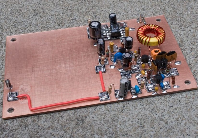
In homebrew electronics, Manhattan style construction is a method of building circuits on a sheet of copper-clad board. Instead of ordering a custom printed circuit board, the builder glues small insulated pads of copper-clad material onto a larger copper surface. Those little pads become connection points for resistors, capacitors, transistors, coils, integrated circuits, and wires.
The name comes from the look of the finished board. Components rise from the copper surface like little buildings on city blocks. The ground plane is the street grid. The pads are the rooftops. The solder joints are, hopefully, not traffic accidents. For a ham radio receiver, this method is especially attractive because radio-frequency circuits appreciate short leads, solid grounding, and easy layout changes.
Manhattan construction is often compared with “ugly construction” or “dead-bug construction.” Ugly construction usually has components soldered directly over a ground plane with minimal structure. Dead-bug construction mounts integrated circuits upside down, with their pins sticking up like the legs of an unfortunate insect. Manhattan style is neater: it gives the builder deliberate islands for non-ground connections while keeping the copper base available as a low-impedance ground.
Why Build a Ham Radio Receiver This Way?
Modern radio gear is amazing. You can buy a software-defined receiver the size of a candy bar, plug it into a laptop, and explore a huge stretch of spectrum before your coffee gets cold. But building a receiver by hand teaches something no shopping cart can provide: how signals actually move through a circuit.
A receiver is not just a box that “gets stations.” It is a chain of decisions. The antenna collects tiny radio-frequency energy. A tuned circuit selects the desired band. A detector or mixer converts radio energy into audio or an intermediate signal. An amplifier makes the recovered sound strong enough for headphones or a speaker. Every stage has a personality. Some behave politely. Others hum, squeal, drift, overload, or act like they were raised by raccoons.
Manhattan style makes that learning process friendly. If a capacitor value needs changing, you replace it. If a lead is too long, you shorten it. If the audio stage oscillates, you can reroute a wire, improve grounding, or add bypassing without redesigning a whole printed circuit board. This makes Manhattan construction ideal for homebrew ham radio, QRP projects, experimental receivers, regenerative sets, and direct-conversion designs.
Receiver Types That Work Well With Manhattan Construction
Regenerative Receivers
A regenerative receiver uses controlled feedback to increase sensitivity and selectivity. In simple terms, a portion of the amplified radio signal is fed back into the tuned circuit. When adjusted carefully, the receiver becomes surprisingly sensitive for its small parts count. When adjusted less carefully, it may howl like a tiny electronic ghost. That is part of the charm, although your family may disagree.
Regenerative receivers are classic learning projects because they reveal the relationship between tuning, feedback, stability, antenna coupling, and audio recovery. Manhattan style helps because the ground plane reduces stray instability, while the open layout makes it easy to experiment with coil placement, tuning capacitors, and detector bias.
Direct-Conversion Receivers
A direct-conversion receiver, sometimes called a zero-IF receiver, mixes the incoming radio signal directly down to audio or baseband. A local oscillator is set near the desired signal frequency, and the mixer produces an audio output representing the difference between the received signal and the oscillator.
Direct-conversion receivers are popular among builders because they can be simple, sensitive, and educational. They also teach the importance of oscillator stability, mixer balance, filtering, shielding, and clean audio gain. Manhattan construction gives the builder a practical way to keep RF paths short while separating the local oscillator, mixer, and audio stages.
Simple Crystal or Fixed-Frequency Receivers
For beginners, a fixed-frequency receiver can be a comfortable first step. Instead of building a wide tuning range, the design may focus on a narrow segment of a band, often using a crystal oscillator or stable local oscillator. This reduces complexity and allows the builder to focus on layout, signal flow, and troubleshooting.
The Anatomy of a Manhattan-Style Ham Receiver
The Copper-Clad Ground Plane
The foundation is usually single-sided copper-clad board. The copper surface acts as the ground plane. In RF work, ground is not just a symbol on a schematic; it is a physical structure. A large, continuous ground plane can reduce unwanted coupling, lower impedance, and help keep the circuit stable.
The Pads or “Islands”
The small glued pads hold non-ground connections. Builders cut these pads from scrap copper-clad board or use commercially made pads. Round pads look tidy. Square pads are easy to cut. Pre-made pads save time and help the finished board look less like it survived a kitchen drawer incident.
The RF Front End
The RF front end includes the antenna input, tuning circuit, and sometimes an RF amplifier. Its job is to accept the signal you want and reject as much unwanted energy as possible. In a simple 40-meter receiver, for example, the front end might include a tuned LC circuit designed around the amateur band near 7 MHz.
The Detector or Mixer
In a regenerative receiver, the detector recovers audio from the radio signal while feedback improves sensitivity. In a direct-conversion receiver, a mixer combines the incoming RF signal with a local oscillator. The result is an audio-frequency signal that can be filtered and amplified.
The Audio Amplifier
After detection or mixing, the signal is weak. An audio amplifier drives headphones or a small speaker. This stage may use discrete transistors, an op-amp, or a simple audio amplifier integrated circuit. Audio stages are forgiving compared with RF stages, but they still need good decoupling and sensible grounding.
Power and Bypassing
Battery power is often preferred for small receivers because it is quiet, portable, and safer than mains-powered supplies. Bypass capacitors near active devices help prevent feedback through the power line. In a receiver, unwanted feedback can turn a calm circuit into a tiny radio opera.
Why Manhattan Style Is So Friendly to RF Circuits
Radio-frequency circuits are sensitive to layout. A wire is not just a wire; it may also be an inductor, an antenna, a feedback path, or a troublemaker wearing copper shoes. Manhattan style encourages short connections and gives the builder a broad ground plane underneath the circuit.
That matters because at RF, long leads and casual wiring can introduce stray capacitance and inductance. These small parasitic effects may shift tuning, reduce stability, or cause oscillation. A Manhattan-style board keeps the circuit compact while still visible and adjustable. You can follow the schematic with your eyes, trace signal flow across the board, and probe stages without digging through a dense commercial PCB.
For experimental ham radio builders, this is gold. You can begin with a known design, then modify it. Try a different coil. Add an RF preamp. Change the audio filter. Improve shielding. Move the oscillator farther from the antenna input. Each change teaches something, even when the lesson is “do not put that wire there unless you enjoy mystery noises.”
Planning the Layout Before Solder Meets Copper
The best Manhattan receivers are not random sculptures. They are planned. Before gluing pads, sketch the circuit in sections: antenna input, tuning network, detector or mixer, oscillator, audio amplifier, and power filtering. Keep RF stages compact. Keep oscillator wiring short and stable. Keep high-gain audio away from sensitive RF input points.
A common approach is to arrange the board so signal flow moves left to right. Antenna input begins at one side. Audio output ends at the other. Power distribution runs along an edge or a central bus, with bypass capacitors returning directly to the ground plane. Grounded component leads should be soldered directly to the copper base when possible.
Coils deserve special attention. A hand-wound inductor can be the heart of a receiver. Mount it securely, keep it away from large metal objects that may detune it, and avoid running unnecessary wires through or near it. Tuning capacitors should be mechanically stable. If touching the tuning knob causes the signal to swing wildly, the circuit may need better shielding, grounding, or isolation.
Parts That Make Sense for a First Build
A beginner-friendly Manhattan-style ham receiver does not require exotic components. Many successful projects use common resistors, ceramic and film capacitors, small-signal transistors, toroids or air-wound coils, audio amplifier chips, diodes, and a variable capacitor or tuning diode. The goal is not to build the fanciest receiver on the planet. The goal is to build one that works, teaches, and invites improvement.
For a simple receiver, consider focusing on one band. The 40-meter amateur band is popular for homebrew projects because it offers plenty of activity, especially for CW and digital signals. Shortwave broadcast bands can also be interesting for receive-only experiments, depending on the design. Remember that receiving is generally different from transmitting: transmitting on amateur bands requires the appropriate license and compliance with regulations.
Useful bench tools include a soldering iron, side cutters, small pliers, multimeter, magnifier, and a way to generate or identify signals. An RF signal generator is helpful but not mandatory for every beginner. Even a known working transmitter nearby, a stable oscillator, or an online frequency reference can help with testing, as long as legal and safe operating practices are followed.
Common Problems and How Builders Think Through Them
No Signal
Start with power. Confirm voltage at each active stage. Check polarity on electrolytic capacitors, transistors, diodes, and ICs. Then verify the audio stage by touching the audio input through a capacitor or using a low-level test signal. If the audio stage works, move backward toward the detector or mixer.
Only Hum or Buzz
Hum may come from a power supply, poor grounding, nearby electronics, or excessive audio gain. Battery operation can help isolate the problem. Keep audio input wiring short and shielded if needed. Add proper decoupling near amplifier stages.
Receiver Oscillates Uncontrollably
Some oscillation is intentional in regenerative receivers, but uncontrolled squealing is not. Look for long leads, poor bypassing, coupling between output and input, or layout that places high-gain stages too close together. Manhattan boards are easy to modify, so move parts, shorten leads, and improve grounding.
Tuning Is Touchy
Touchy tuning can come from unstable mechanical mounting, hand capacitance, poor oscillator buffering, or a tuning range that is too wide. A reduction drive, smaller tuning capacitor, bandspread capacitor, or better shielding can make the receiver much more pleasant to use.
Strong Stations Overload the Receiver
Simple receivers can overload when strong nearby signals enter the front end. Better input filtering, an RF attenuator, improved antenna coupling, or a more selective tuned circuit can help. In receiver design, sensitivity is wonderful, but too much uncontrolled signal is like inviting the entire marching band into your headphones.
Safety and Legal Notes for New Builders
A receive-only project is one of the safest ways to enter ham radio homebrewing, but basic workshop care still matters. Use low-voltage battery supplies for early experiments. Avoid working with mains voltage unless you are trained and supervised. Solder in a ventilated area, keep hot tools away from clutter, and wear eye protection when cutting copper-clad board or trimming component leads.
Also understand the difference between receiving and transmitting. Listening to many radio signals is generally accessible with ordinary receivers, but transmitting on amateur bands requires the proper amateur radio license. In the United States, amateur radio is regulated under FCC rules, and licensed operators are responsible for their transmissions. A homemade receiver is a great educational project; a homemade transmitter adds legal and technical responsibilities.
Why This Old-School Method Still Matters
Manhattan construction survives because it solves a real problem: RF builders need a quick, stable, flexible way to prototype circuits. Breadboards are convenient for low-frequency digital experiments, but they are usually poor choices for RF receivers. Their long internal contacts and stray capacitance can make radio circuits behave unpredictably.
A custom PCB is excellent when the design is finished, but early experiments need freedom. Manhattan style lives in the sweet spot. It is cleaner than all-air wiring, faster than PCB design, more RF-friendly than solderless breadboards, and more educational than simply assembling a black-box module.
It also looks wonderful. A well-built Manhattan receiver has the beauty of a hand-drawn map. You can see the logic. You can see the mistakes. You can see the places where the builder changed their mind, added a bypass capacitor, or moved a transistor after discovering that physics had filed a complaint.
Experience Notes: Building and Using a Manhattan-Style Ham Radio Receiver
The first experience most builders have with a Manhattan-style ham radio receiver is not instant success. It is usually a sequence of small victories. The power LED lights up. The audio amplifier hisses. The tuning capacitor changes the noise slightly. Then, after a bit of adjustment, a faint signal appears. It may be Morse code, a shortwave broadcast, a digital warble, or a distant voice floating out of the static. That moment is magic. Not polished, not commercial, not wrapped in plasticjust magic.
One of the biggest lessons is that layout matters as much as the schematic. A circuit diagram may show two parts connected by a clean line, but on the bench that line has length, position, and personality. Move a wire half an inch and the receiver may become quieter. Rotate a coil and the tuning may improve. Add a bypass capacitor near the audio stage and an annoying motorboat sound may disappear. Manhattan construction makes these lessons visible because the circuit is open and honest. It does not hide behind solder mask and silkscreen.
Another experience is learning patience with tuning. Simple receivers, especially regenerative designs, reward gentle hands. The regeneration control may need a delicate touch. The tuning capacitor may cover a wide range, so a tiny movement can jump across several signals. At first, this feels frustrating. Later, it becomes part of the craft. You learn to slow down, listen carefully, and recognize the difference between band noise, local interference, and a real signal.
Headphones can make the experience more personal. With a small homebrew receiver, signals often sound intimate, like you have opened a secret side door into the radio spectrum. Commercial receivers may sound cleaner, but a handmade receiver has character. It may drift a little as it warms up. It may prefer one antenna over another. It may behave differently when moved from the bench to a picnic table outside. Each quirk teaches you something about grounding, shielding, antenna coupling, and component stability.
The best practical habit is to build in stages. Do not solder the entire receiver and then wonder why silence has moved in permanently. Build the audio amplifier first and test it. Then add the detector or mixer. Then add the oscillator or regenerative stage. Then connect the tuned circuit and antenna input. After each stage, pause and verify. This staged approach turns troubleshooting into a set of small puzzles instead of one giant mystery novel with half the pages missing.
Manhattan style also encourages reuse. A board that begins as a simple receiver may later gain an RF preamp, a sharper audio filter, a better tuning arrangement, or a nicer enclosure. The builder can scrape, desolder, reglue, and reroute. That flexibility is why so many homebrewers keep returning to the method. It is not just a construction technique; it is a thinking technique. It invites experimentation without demanding perfection first.
In the end, a Manhattan-style ham radio receiver is less about saving money and more about gaining understanding. You build it, test it, improve it, and slowly begin to hear not only stations, but the circuit itself. Every hiss, whistle, peak, null, and sudden clear signal becomes feedback from the real world. That is the joy of homebrew radio: the bench becomes a classroom, the receiver becomes a teacher, and the air around you becomes a textbook written in waves.
Conclusion
A ham radio receiver Manhattan style is a perfect project for curious builders who want to understand radio from the inside out. It combines practical RF layout, hands-on soldering, signal tracing, and old-school experimentation in a format that is forgiving enough for learners and flexible enough for experienced operators.
Whether you choose a regenerative receiver, a direct-conversion design, or a simple fixed-frequency project, Manhattan construction gives you a solid ground plane, visible signal paths, and the freedom to modify the circuit as your understanding grows. It may not look like a factory-made board, but that is the point. It looks like learning. It looks like invention. And if the pads resemble a tiny city skyline, congratulationsyou have just built your own little radio Manhattan.