Table of Contents >> Show >> Hide
- What “Old Fashioned Way” Really Means
- How an Old-School Electronic Dice Works
- Why This Project Still Matters
- Design Details That Separate a Good Build From a Glitchy One
- Discrete Logic vs. Microcontroller Dice
- Best Uses for an Old-Fashioned Electronic Dice
- Final Thoughts: Why the Old Way Still Feels Fresh
- Experience Section: What Building and Using One Actually Feels Like
Some gadgets try very hard to look smart. An old-school electronic dice does not. It blinks, it counts, it pauses dramatically, and then it tells you whether fate has handed you a one or a six. No app. No touchscreen. No firmware update. No mysterious cloud service deciding your luck from a server farm three time zones away. Just honest components doing exactly what they were designed to do.
That is the charm of electronic dice built the old fashioned way. Instead of using a microcontroller and a few lines of code, this style of project relies on classic parts such as a 555 timer, a decade counter, resistors, capacitors, LEDs, and a little clever wiring. It turns a simple game of chance into a miniature lesson in logic, timing, and hardware design. Better yet, it is the kind of circuit that teaches you what is happening rather than hiding the fun behind software. If modern electronics often feels like magic, this project feels like craftsmanship.
What “Old Fashioned Way” Really Means
When builders talk about doing something the old fashioned way, they usually mean building it with discrete logic instead of programmable brains. In an electronic dice project, that means the job is divided among physical components. One part creates pulses. Another part counts those pulses. Another part lights the LEDs in the familiar pip pattern of a die face. The result is surprisingly elegant. It is not primitive. It is just wonderfully literal.
An old-fashioned electronic dice usually begins with a pulse generator. That pulse train acts like a drumbeat for the circuit. While the “roll” is active, the counter moves rapidly through states. When the rolling stops, the final state remains on the LEDs, giving you a number from one to six. That simple action is the whole show, but it reveals several core ideas in electronics: oscillation, counting, display logic, power stability, and switch behavior.
The Classic Parts List
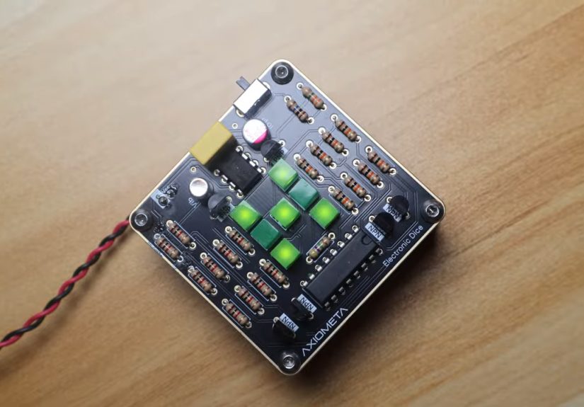
The heart of many vintage-style builds is the famous 555 timer. It is the little legend that refuses to retire. In this project, the 555 is often configured as an astable oscillator so it continuously produces pulses while the dice is rolling. Those pulses are fed into a CD4017 decade counter, which steps through outputs one at a time. Add a handful of LEDs, a few current-limiting resistors, some diodes or smart wiring for pip patterns, a pushbutton or vibration trigger, and a couple of capacitors, and you have the ingredients for a circuit that feels delightfully mechanical even though it is fully electronic.
There is something deeply satisfying about this bill of materials. Every part earns its spot. The resistor is not decorative. The capacitor is not an afterthought. The counter is not pretending to be clever. Each component does a visible job, which is why this project remains such a favorite for hobbyists, students, and anyone who enjoys circuits that are easy to explain but still fun to perfect.
How an Old-School Electronic Dice Works
The Pulse Generator: Where the Roll Begins
The 555 timer acts like the project’s metronome. In astable mode, it repeatedly switches between high and low output states, generating a stream of clock pulses. The speed depends on resistor and capacitor values, which means the personality of your dice is literally baked into the hardware. Want it to whirl through values fast enough to feel random? Choose components for a quick oscillation. Want a more theatrical slowdown? Pair the clock section with a release circuit or trigger network that lets the display coast to a stop.
This is one reason old-fashioned electronic dice feels so hands-on. In software, you might change a variable. In hardware, you change the soul of the circuit by swapping a capacitor. It is electronics with fingerprints on it.
The Counter: Turning Pulses Into Possibilities
Once the pulses leave the 555 timer, the CD4017 takes over. This chip advances one decoded output for each clock pulse, which makes it perfect for LED sequencing. In a basic dice design, the counter is arranged so only six useful states are used. Each state corresponds to one face of the die. Instead of showing numbers with a seven-segment display, many builders prefer the classic pip layout because it looks more playful and instantly recognizable.
Here is where the circuit gets charmingly clever. A standard die face uses seven LED positions: three on the left, three on the right, and one in the center. By combining outputs or steering current with diodes, each count state can illuminate the right pattern. One lights the center LED. Two lights opposite corners. Three adds the center. Four uses four corners. Five adds the middle. Six lights the left and right columns without the center. It is visual logic, not software logic, and that is exactly why it is so fun.
Why It Stops at Six Instead of Counting to Ten
The CD4017 is a decade counter, which means it naturally supports ten decoded outputs. A die, however, only needs six outcomes unless you are building the world’s nerdiest role-playing accessory and aiming for a d10. For a standard electronic dice, the circuit is typically wired so the counter resets after the sixth active state. That way, the chip never wanders off into outputs seven, eight, nine, and ten like a very confused casino employee.
This reset trick is one of the best examples of old-school design thinking. You do not need a processor to “know” how many sides a die has. You simply wire the counter so the seventh step forces a reset. The hardware enforces the rules.
Why This Project Still Matters
At first glance, building electronic dice with classic logic might seem unnecessary. After all, a tiny microcontroller could do the job with less wiring. That is true in a narrow sense, but it misses the bigger point. Projects like this are still valuable because they teach fundamental electronics in a concrete, memorable way.
When you build a discrete logic dice, you learn how oscillators behave, how counters advance, how LEDs need proper current limiting, why switches bounce, and why power rails need decoupling. You also learn that “simple” circuits are often simple only after someone has already solved a dozen tiny problems. That is excellent training for bigger projects.
There is also the human factor. A breadboard full of jumper wires and blinking LEDs feels alive in a way that a black-box module often does not. You can watch the clock pulse become a count, and the count become a pattern, and the pattern become a game result. That transparency is catnip for curious builders.
Design Details That Separate a Good Build From a Glitchy One
Debouncing the Trigger
Pushbuttons are not as polite as they look. When you press or release them, their contacts can bounce electrically for a brief moment, creating multiple unintended transitions. In an electronic dice, that can make the roll start or stop unpredictably. If the switch is used directly, your “random” result may be less charming and more chaotic.
That is why good old-fashioned designs often include a simple debounce approach, such as an RC network, a one-shot stage, or a carefully chosen trigger arrangement. The goal is to make the roll feel crisp: one press, one event, no drama from the button itself. Unless your design philosophy is “Let the switch panic and we’ll call it feature-rich.”
Choosing the Right LED Resistors
LEDs are the stars of the show, but they are not invincible. Each one needs a resistor to limit current and protect both the LED and the driving circuit. This is one of those tiny details that beginners sometimes skip exactly once. After that, they become lifelong believers in resistor math.
Proper current limiting also helps the display look balanced. If one pip is visibly brighter than the others, the finished dice feels sloppy even when the logic works perfectly. A thoughtful builder chooses resistor values that keep brightness consistent and safe for the supply voltage being used, whether that is a 5-volt bench supply, a battery pack, or a simple regulated source.
Power Stability and Decoupling
Small digital circuits can still be surprisingly noisy. A 555 timer switching quickly can inject spikes onto the power rail, and counters do not appreciate being fed unstable voltage. That is why decoupling capacitors matter. A humble ceramic capacitor placed close to the integrated circuits can dramatically improve reliability by smoothing little disturbances before they become full-blown misbehavior.
This is the kind of detail seasoned builders never ignore. To a newcomer, a decoupling capacitor may look like a boring extra part. To someone who has spent an hour chasing phantom glitches, it looks like peace.
Breadboard Layout Matters More Than People Expect
Electronic dice is often built on a solderless breadboard first, and that makes it accessible. It also means layout matters. Long jumpers, crowded power rails, and accidental misrouting can create problems that look like logic errors but are really just wiring mistakes. The neatest builds are often the best-performing builds because clear layout reduces confusion and noise at the same time.
There is a certain irony here: a circuit designed to simulate randomness actually rewards obsessive organization. The dice may be random. The wiring should not be.
Discrete Logic vs. Microcontroller Dice
A microcontroller-based electronic dice is compact, flexible, and easy to customize. It can add sound, motion sensing, sleep modes, and fancy animations with minimal hardware. That is great. But it also changes the nature of the project. Much of the behavior moves into code, which means the learning shifts from circuit design to programming.
The old-fashioned version keeps the lesson in plain sight. You can probe the oscillator with a meter or scope. You can see the counter outputs step. You can trace the display logic with your eyes. If something fails, the fix is usually in the wiring or component values rather than hidden in a firmware loop. For educational value, tactile satisfaction, and pure retro appeal, discrete logic still wins a lot of hearts.
There is also a philosophical advantage. Building electronic dice the old way reminds us that useful behavior can emerge from modest hardware. You do not always need a processor to make something feel smart. Sometimes timing plus logic plus LEDs is enough to create a device that feels playful, understandable, and complete.
Best Uses for an Old-Fashioned Electronic Dice
This project is ideal for beginner electronics classes, maker workshops, hobby desks, and nostalgic weekend builds. It is also a terrific conversation starter. People recognize what it does instantly, but they still lean closer because blinking pips are irresistible. It can live as a learning project, a desk toy, a game-night accessory, or even a stepping stone toward more advanced discrete-logic work.
It also scales nicely. A simple version can use a pushbutton and a breadboard. A more refined version can add a vibration switch, a latching power stage, a printed enclosure, or a compact soldered PCB. Some builders go further and create dual-dice versions for board games. Others stay faithful to the minimalist spirit and keep it as a tiny lesson in timing and counting. Both approaches are valid. The beauty is that the concept stays understandable no matter how far you take it.
Final Thoughts: Why the Old Way Still Feels Fresh
Electronic dice built the old fashioned way is more than a novelty project. It is a compact demonstration of how classic electronics can still be practical, educational, and genuinely delightful. The 555 timer gives it a heartbeat. The counter gives it memory. The LEDs give it personality. The builder gives it character.
In a world full of invisible software, this kind of project is refreshingly honest. You can point to each part and explain what it does. You can improve it with better layout, cleaner triggering, or smarter display wiring. You can learn from every mistake. And when the LEDs settle on a final roll, you get more than a number. You get proof that simple hardware, thoughtfully arranged, still has plenty of magic left in it.
Experience Section: What Building and Using One Actually Feels Like
There is a special kind of satisfaction that comes from building an electronic dice with classic parts instead of modern code-heavy hardware. At first, the project looks almost too simple to be exciting. A timer chip, a counter, a few resistors, seven LEDs, and some wiring do not exactly scream “cutting-edge innovation.” Then you start assembling it, and the personality of the thing begins to emerge.
The first memorable moment is usually not success. It is confusion. Maybe the LEDs refuse to count in the right order. Maybe one corner pip glows when it absolutely should not. Maybe the whole circuit seems to roll forever as if it has developed a gambling problem. Those early hiccups are part of the experience, and oddly enough, they are what make the project enjoyable. Every fix feels earned. You are not just uploading new code and hoping for the best. You are learning the behavior of real components, one clue at a time.
Once the oscillator starts pulsing properly, the project becomes addictive. You tap the button and watch the lights race through the possible outcomes. Even on a breadboard, it feels like a tiny machine with a pulse. The LEDs do not merely turn on and off. They perform. The quick flicker before the final number lands gives the circuit a little suspense, almost like it is taking a theatrical pause before revealing your fate. It is hard not to grin the first time it lands cleanly on five and stays there.
Using the finished device is a different experience from using a normal die or a phone app. A plastic die is instant, quiet, and familiar. An app is convenient but forgettable. A homemade electronic dice has drama. It clicks into action, flashes across possibilities, and settles with visible confidence. People tend to react to it the same way: they smile, then immediately ask how it works. That is the magic of transparent electronics. The device does its job, but it also invites curiosity.
Another great part of the experience is how physical the project feels. You notice how component choices affect behavior. Swap a capacitor and the roll speed changes. Improve the button wiring and the trigger feels cleaner. Add better decoupling and the display becomes calmer and more reliable. The project teaches you that electronics is not just theory. It is texture, timing, placement, and tiny decisions that shape the final experience.
There is also a nostalgic pleasure in using a design that does not depend on software. Nothing needs pairing. Nothing needs flashing. Nothing needs a menu. The circuit simply exists, ready to do one charming job over and over. That limitation is part of the appeal. It does not try to be a smart home hub, a Bluetooth accessory, or a platform. It is a blinking electronic dice, and it commits to the bit with admirable confidence.
In the end, the best experience of all may be what the build leaves behind. You finish with more than a game accessory. You finish with a small, working lesson in classic electronics and a stronger intuition for how circuits behave in the real world. And every time you press the button and watch the LEDs dance, you remember that old-fashioned design still knows how to put on a show.
Note: This HTML is body-ready and cleaned for direct web publishing.