Table of Contents >> Show >> Hide
- Why SDR Transmitters Need Discipline
- What “Discipline” Means In SDR
- The Classic Problem: Frequency Drift
- GPSDO: The Popular Way To Tame An SDR Clock
- External Reference Inputs: Small Connector, Big Consequences
- Clock Accuracy, Stability, Jitter, And Phase Noise
- Gain Discipline: Do Not Drive The SDR Like A Rental Car
- Filtering: The Bouncer At The RF Door
- Software Discipline: Your Flowgraph Can Betray You
- Legal And Practical Spectrum Hygiene
- Example: A Stable SDR For Satellite Work
- A Practical Discipline Checklist
- Common Mistakes That Make SDR Transmitters Misbehave
- Field Experience: What Bringing Discipline To An SDR Transmitter Feels Like
- Conclusion: A Disciplined SDR Is A Better Neighbor
- SEO Tags
Software-defined radio has made RF experimentation wonderfully accessible. But when an SDR transmitter starts drifting off frequency, splattering spurious signals, or behaving like it had too much coffee, it needs one thing: discipline. In SDR terms, that usually means a cleaner clock, a smarter setup, and a healthy respect for spectrum hygiene.
Why SDR Transmitters Need Discipline
A software-defined radio transmitter is a tiny miracle. Instead of building a separate analog circuit for every mode, filter, and modulation scheme, you create much of the signal in software and hand it to RF hardware for conversion into the real world. That is elegant, flexible, and dangerously easy to underestimate.
The trouble is that RF does not care how pretty your flowgraph looks. If the transmitter clock is unstable, the generated signal can wander. If the sample rate is wrong, the bandwidth can shift. If the gain is too hot, the output can become distorted. If filtering is lazy, harmonics and spurious emissions can leave the party through the antenna port. Suddenly, your “educational experiment” has the manners of a leaf blower in a library.
Bringing discipline to an SDR transmitter means controlling the things that decide whether your signal is clean, stable, and legally usable. The most important areas are frequency reference, clock stability, gain staging, filtering, measurement, and operating responsibility. In other words: less guessing, more measuring.
What “Discipline” Means In SDR
In RF engineering, a disciplined oscillator is an oscillator corrected by a more reliable reference. A GPS-disciplined oscillator, often called a GPSDO, uses satellite timing to steer a stable local oscillator such as an OCXO. The result is a reference that can provide excellent long-term accuracy while keeping short-term stability good enough for demanding radio work.
Many SDRs use an internal crystal oscillator as their timing source. That crystal feeds internal phase-locked loops, local oscillators, digital sample clocks, and other timing circuits. If the reference is slightly off, every derived frequency can inherit that error. At low frequencies, a few parts per million may seem harmless. At UHF, microwave, or satellite frequencies, that small error can become very noticeable.
Think of the SDR clock as the drummer in a band. If the drummer rushes, the whole band rushes. If the drummer drifts, the singer looks confused, the guitar player blames the monitor mix, and the audience quietly leaves. A disciplined reference gives the drummer a metronome.
The Classic Problem: Frequency Drift
Frequency drift is one of the first issues experimenters notice when using affordable SDR transmitters. A device may start close to the desired frequency, then slowly move as the hardware warms up. Temperature changes affect crystals. USB-powered devices can see supply variations. Enclosures, airflow, and even sunlight on the bench can change the thermal behavior of the radio.
For casual receiving, drift is annoying. For transmitting, drift is more serious. A signal that starts in the right place can slide toward another user, move outside the expected passband, or make narrow digital modes fail. On satellite links and microwave operations, the effect is even more dramatic because small reference errors are multiplied at higher RF frequencies.
This is why SDR transmitter discipline is not just an upgrade for perfectionists. It is part of responsible operation. A stable signal is easier to receive, easier to decode, easier to monitor, and less likely to bother someone else. The spectrum is shared space; nobody wants the RF equivalent of a shopping cart parked sideways in the aisle.
GPSDO: The Popular Way To Tame An SDR Clock
A GPS-disciplined oscillator is one of the most common tools for improving SDR frequency accuracy. Many lab-grade and higher-end SDR systems accept a 10 MHz external reference and a 1 pulse-per-second timing signal. Some devices, such as various USRP models, can use external reference inputs, onboard GPSDO modules, or network-based timing methods to keep multiple radios aligned.
Not every SDR expects the same reference. Some devices use a 10 MHz reference input. Some expect a 40 MHz reference. Others may require a particular voltage level, waveform, connector, or configuration setting. This is where discipline begins before the clock is even plugged in: read the documentation, confirm the hardware revision, and avoid assuming that every SMA connector is a magical “make radio better” hole.
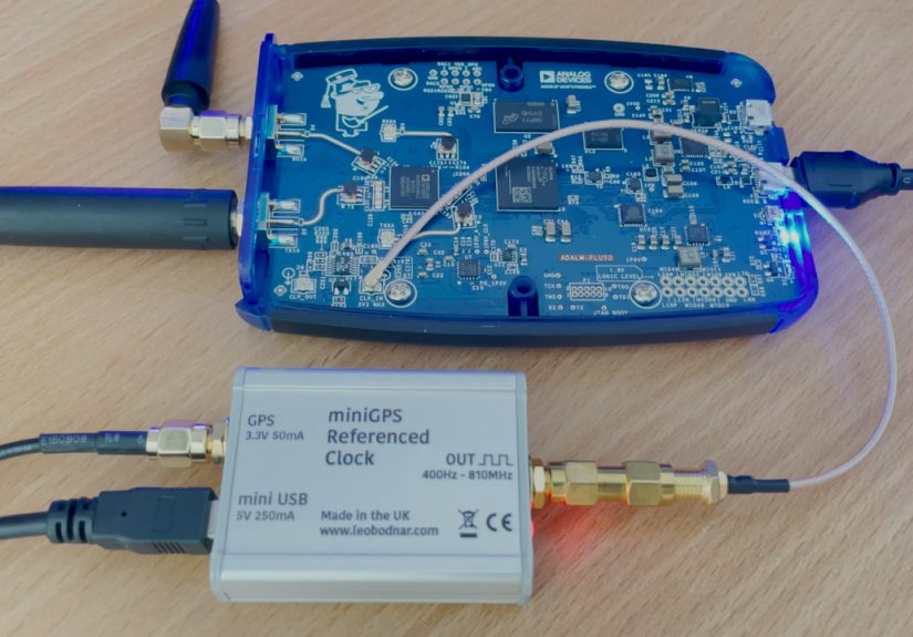
The ADALM-Pluto, for example, is widely used by experimenters because it is compact, affordable, and flexible. Its clocking arrangement has made it popular for projects where an external reference improves stability. On some PlutoSDR revisions, using an external clock can be straightforward; on others, hardware differences and configuration details matter. The lesson is simple: the principle is universal, but the implementation is device-specific.
External Reference Inputs: Small Connector, Big Consequences
An external reference input lets the SDR derive its internal clocks from a better source. In practice, that may mean connecting a GPSDO, rubidium standard, lab signal generator, or shared clock distribution system. When it works, the SDR’s transmitter lands closer to the intended frequency and stays there more reliably.
The detail that catches many people is signal compatibility. A reference input may expect a sine wave or square wave. It may require a specific amplitude. It may be high impedance or 50 ohms. It may tolerate only a narrow frequency range. Feeding the wrong level or wrong frequency into a reference input is not “bold experimentation.” It is a quick way to create smoke, silence, or a new decorative paperweight.
For multi-radio systems, a shared clock can also help multiple SDRs remain coherent. This matters for direction finding, MIMO experiments, distributed receivers, and phase-sensitive measurements. But synchronization is more than frequency. Systems may also need shared timing, hardware triggers, sample alignment, and software support. A shared 10 MHz reference can solve one problem while leaving three more waiting politely in the hallway.
Clock Accuracy, Stability, Jitter, And Phase Noise
Clock quality is not a single number. Accuracy tells you how close the oscillator is to the intended frequency. Stability tells you how much it changes over time. Jitter describes timing uncertainty. Phase noise describes short-term random frequency fluctuations around the carrier. For SDR transmitters, all of these matter.
A transmitter can be accurate in the long term but noisy in the short term. It can be stable over a few seconds but offset from the desired frequency. It can look fine on a casual receiver but show ugly close-in phase noise on better test equipment. That is why a GPSDO is helpful but not a magic wand. A poor clock distribution layout, bad cables, ground noise, overloaded stages, or cheap switching supplies can still make a signal messy.
Good SDR transmitter design treats the reference clock as part of the RF chain, not as an afterthought. If the clock is dirty, the signal can be dirty. If the clock is solid, the rest of the system has a much better chance of behaving.
Gain Discipline: Do Not Drive The SDR Like A Rental Car
Clock discipline keeps the transmitter on frequency, but gain discipline keeps it clean. SDR transmit chains usually include digital amplitude settings, DAC output levels, mixers, variable-gain amplifiers, and sometimes external power amplifiers. Pushing every slider to maximum does not make the signal better. It usually makes it wider, uglier, and less welcome.
Overdrive causes nonlinear distortion. In plain English, the transmitter starts creating energy where you did not ask for it. Harmonics, intermodulation products, shoulders around digital signals, and broadband noise can appear. A waterfall display may turn from a neat line into something that looks like a raccoon stepped in wet paint and ran across the spectrum.
A disciplined SDR transmitter uses just enough gain for the job. The cleanest signal is often produced below maximum output, followed by a properly filtered and linear external amplifier if more power is required. The goal is not to make the loudest signal on the band. The goal is to make the cleanest signal that accomplishes the communication task.
Filtering: The Bouncer At The RF Door
Filtering is the bouncer that keeps unwanted RF from leaving the building. Low-pass filters reduce harmonics above the operating frequency. Band-pass filters pass only the intended slice of spectrum. Reconstruction filters help smooth DAC output. In SDR transmitters, filtering is not optional decoration; it is how you keep digital convenience from becoming analog chaos.
Affordable SDRs are often designed as development tools, not finished transmitters for every service and band. Their raw output may need external filtering before it is connected to an antenna or amplifier. This is especially important when using wideband devices that can tune across large frequency ranges. Flexibility is wonderful, but a wide-open RF front end can also provide wide-open opportunities for mistakes.
Before transmitting over the air, a responsible operator checks the signal into a dummy load, uses attenuation where appropriate, and verifies the spectrum with suitable test equipment. A spectrum analyzer, calibrated SDR receiver, or service monitor can reveal spurs and harmonics that an ordinary receiver may miss. The antenna should be the final step, not the first witness.
Software Discipline: Your Flowgraph Can Betray You
Software-defined radio makes signal generation feel deceptively simple. Drop in a source block, add modulation, connect a sink, and suddenly the computer is “transmitting.” But the flowgraph has to respect sample rates, interpolation, filtering, amplitude scaling, and hardware clock settings.
One common mistake is assuming that software has automatically selected the external clock source. Some frameworks and drivers require explicit settings. Others hide hardware options in device arguments or separate configuration tools. A GPSDO connected to the SDR does nothing if the SDR is still using its internal clock. That is like buying a gym membership and then doing push-ups next to the vending machine.
Another common issue is sample-rate mismatch. If the software signal is generated at one rate and the hardware expects another, the transmitted waveform may not have the intended bandwidth or pitch. Filters designed for one sample rate may perform badly at another. Good SDR work includes checking each stage of the signal path before blaming the hardware.
Legal And Practical Spectrum Hygiene
Transmitting RF energy is regulated for good reason. In the United States, amateur radio transmitters must meet emission standards, and operators are responsible for ensuring that their stations do not cause harmful interference. Similar rules exist in other countries. Even on unlicensed bands, devices must follow applicable technical limits.
The important point is this: an SDR is not automatically a compliant transmitter just because the circuit board was sold by a reputable company. Many SDRs are development platforms. They can generate signals, but the user is responsible for how, where, and whether those signals are transmitted. Licensing, frequency authorization, bandwidth, power level, filtering, and identification all matter.
A disciplined SDR transmitter stays inside the rules. It uses authorized frequencies, appropriate power, clean modulation, proper filtering, and verified output. The best operators are not the ones who make the spectrum analyzer scream. They are the ones whose signals appear exactly where expected, at the necessary strength, with no extra surprises.
Example: A Stable SDR For Satellite Work
Satellite communication is a perfect example of why discipline matters. A station working through a narrowband satellite transponder needs frequency accuracy and stability. The uplink and downlink may be in microwave bands where oscillator error becomes highly visible. Add Doppler shift, transverter offsets, and narrow digital modes, and an undisciplined SDR can become a moving target.
Experimenters using SDRs such as the ADALM-Pluto for satellite work often improve performance by locking the transmitter reference to a GPSDO or other precision source. The goal is not merely to brag about a fancy clock. The goal is to reduce drift so the transmitted signal remains usable and respectful of the shared transponder.
This is especially relevant for QO-100-style operation, where stable station equipment helps keep narrowband activity orderly. A clean, disciplined signal makes life easier for everyone listening. A drifting signal forces others to chase it. Nobody wants to play “Where did the carrier go?” during a contact.
A Practical Discipline Checklist
1. Confirm The SDR’s Reference Options
Check whether the SDR supports an external clock, what frequency it expects, what voltage level is safe, and whether software configuration is required. Do not rely on forum folklore when official documentation is available.
2. Use A Suitable Reference Source
A GPSDO, OCXO, rubidium standard, or lab-grade frequency reference can improve stability. Choose the source based on the application. A simple local experiment may not need the same discipline as satellite, microwave, or coherent multi-radio work.
3. Verify The Clock Is Actually Selected
Many setups fail because the external reference is physically connected but not active in software. Use device utilities, driver reports, or measured frequency output to confirm the SDR is locked to the intended reference.
4. Keep Gain Conservative
Start low, increase carefully, and watch the spectrum. Clean output beats maximum output. If more power is needed, use a linear amplifier designed for the signal type and band, followed by appropriate filters.
5. Measure Before Radiating
Use a dummy load, attenuators, and monitoring equipment. Look for harmonics, spurs, excessive bandwidth, and frequency offset. The best time to discover a problem is before the antenna is connected.
Common Mistakes That Make SDR Transmitters Misbehave
The first mistake is assuming the factory oscillator is “close enough” for every job. It may be fine for casual experiments but inadequate for narrowband or high-frequency operation. The second mistake is confusing receive stability with transmit stability. A receiver can often be tuned around a problem; a transmitter exports the problem to everyone else.
The third mistake is ignoring thermal behavior. An SDR that is accurate after thirty minutes may be off during the first five. Letting equipment warm up before critical operation is an old radio habit that remains useful. Modern hardware may be digital, but crystals still have feelings, mostly about temperature.
The fourth mistake is treating spectrum displays as decoration. A waterfall is not just pretty blue and yellow wallpaper. It is diagnostic information. If the signal has shoulders, extra carriers, unexpected bumps, or wandering frequency, the display is trying to tell you something. Listen to it before someone else has to.
Field Experience: What Bringing Discipline To An SDR Transmitter Feels Like
The first time you discipline an SDR transmitter, the improvement can feel almost suspicious. Before the upgrade, the signal behaves like it has weekend plans: it starts near the right frequency, drifts a little, warms up, drifts again, and then settles only after you have lost patience. After a good external reference is configured correctly, the signal suddenly stands still. It is not glamorous. It does not make a dramatic movie trailer sound. It simply stops wandering, which in RF work is surprisingly satisfying.
A typical bench experience starts with a modest SDR, a laptop, a short coax jumper, a dummy load, and a monitoring receiver or spectrum analyzer. At first, you transmit a low-power test signal into the dummy load and notice the offset. Maybe the carrier is a few hundred hertz away from where it should be. Maybe it is several kilohertz off at a higher frequency. Then the device warms up, and the signal moves again, because apparently even radios need time to find themselves emotionally.
Next comes the disciplined reference. The GPSDO is connected, the SDR settings are changed, and the software is restarted because software enjoys ceremony. Then you check again. If everything is right, the offset shrinks dramatically, and drift becomes far less obvious. If nothing changes, the problem is usually not the laws of physics. It is more likely that the SDR never switched to the external clock, the reference level is wrong, the device argument is missing, or the wrong hardware revision is being treated like the right one.
One useful habit is to write down the entire setup: reference frequency, clock source setting, sample rate, transmit frequency, gain, filter chain, driver version, and warm-up time. This sounds boring until the day everything works beautifully, you shut it down, and two weeks later you cannot remember which tiny setting made the magic happen. A notebook is cheaper than rediscovering your own project like an archaeologist with a soldering iron.
The biggest lesson from real SDR transmitter work is that discipline is a system behavior. A GPSDO helps frequency accuracy, but it does not fix overdrive. A beautiful band-pass filter helps spectral purity, but it does not correct a wrong sample rate. A clean flowgraph helps modulation quality, but it does not make an illegal transmission legal. The winning setup is boring in the best possible way: stable clock, verified settings, conservative gain, appropriate filters, measured output, and authorized operation. When all of those line up, the transmitter stops feeling like a science fair volcano and starts behaving like a real radio instrument.
Conclusion: A Disciplined SDR Is A Better Neighbor
Bringing discipline to an SDR transmitter is about more than adding a fancy timing box. It is a mindset. A clean SDR transmitter starts with a stable reference, but it also depends on thoughtful software settings, careful gain control, proper filtering, and measurement before transmission. The result is a signal that lands where it should, stays where it belongs, and does not drag unwanted RF clutter along for the ride.
For hobbyists, students, engineers, and amateur radio operators, this is where SDR becomes truly powerful. The same flexibility that can create messy signals can also create excellent ones when handled carefully. With a GPSDO or other suitable reference, correct clock configuration, and responsible RF practice, an SDR transmitter can move from “interesting gadget” to “trustworthy radio tool.”
In short, discipline turns an SDR transmitter from a clever box of possibilities into a well-behaved citizen of the spectrum. And in radio, being well-behaved is not boring. It is how everyone else gets to keep enjoying the band, too.